


 En
 English
 русский
 Español
 عربى

MRL Traction Technology in Home Elevators: Space Savings and Controller Placement
Posted by Admin | 10 Nov
Content
- 1 What MRL Traction Technology Changes in a Home
- 2 Where the Space Savings Really Come From
- 3 Controller Placement: The Detail That Decides the Layout
- 4 Fitting MRL into Restricted Residential Spaces
- 5 Service Access, Safety, and Code Checks
- 6 What to Confirm Before You Choose an MRL Home Elevator
- 7 Frequently Asked Questions
A machine roomless (MRL) traction elevator is often presented as a simple space-saving upgrade for a private home: remove the machine room, gain usable floor area, and keep the smooth ride of traction. In practice, the benefit depends on how the whole system is arranged. The drive sheave, ropes, counterweight, car, and controller must still fit somewhere, and each component shapes the shaft, the landing, and the service plan.
For architects, builders, and homeowners planning a villa or residential retrofit, the practical question is not only how much space an MRL elevator saves, but where the controller goes and what space that location really requires. This guide explains the spatial logic, controller placement options, and checks that keep an MRL home elevator workable after installation.
What MRL Traction Technology Changes in a Home
A conventional traction elevator uses a separate machine room, often a penthouse or rooftop enclosure, to house the driving machine and related equipment. An MRL layout integrates the traction machine within the top of the hoistway and uses a compact controller arrangement. In a private residence, that can remove a bulky rooftop structure and release space for a roof terrace, loft, storage area, or better roofline.
MRL describes the machine room arrangement, not a separate drive principle. The elevator still uses a traction sheave, ropes, and a counterweight, so car size, travel height, overhead clearance, and pit depth must be coordinated. For a closer view of the design logic, see Dong'ao's MRL technology overview.
Where the Space Savings Really Come From
The savings are not limited to deleting one room. They come from reorganizing several zones at once, and each zone has a different effect on the home.
| Planning zone | Conventional machine-room layout | MRL opportunity and check |
|---|---|---|
| Machine room | Separate penthouse or roof room with access, walls, and ventilation | Remove the room and recover roof or upper-floor area |
| Hoistway top | Extra height for the machine room and equipment | Use a compact top-of-shaft layout, but verify overhead clearance |
| Controller | Located in the machine room with front access | Use a shaft-mounted cabinet, landing cabinet, or adjacent closet |
| Interior landing | Equipment kept away from living space | A small cabinet or service zone may offset part of the shaft gain |
The useful measure is net usable floor area, not shaft area alone. A narrower hoistway can still consume a closet, a section of wall, or part of a utility room if the controller needs a landing-side cabinet. Early layout drawings should show the car envelope, counterweight, door swing, controller cabinet, and service clearance together.
For a typical villa shaft, a gantry-style traction layout is often the starting point because it can use a rectangular hoistway efficiently and leave a practical car envelope.
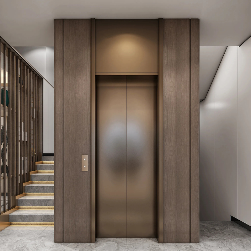 Traction Gantry Elevator for Villas and DuplexesA gearless traction home elevator with gantry layout, steel-rope lifting and 2F–4F options for rectangular villa shafts and practical car envelopes.View Product →
Controller Placement: The Detail That Decides the Layout
The controller is not the same as the traction machine. It contains control boards, power switching, diagnostic points, and emergency operation interfaces. Its location affects heat management, dust exposure, cable routes, service access, and the amount of interior wall or closet space the home must give up. An MRL elevator may place the controller in the hoistway, but that is not automatic; the final position must suit the product design and the building.
Inside the Hoistway
A shaft-mounted controller can keep the landing clean and shorten cable runs. The cabinet must not intrude into car travel, counterweight movement, door operation, or required clearances. It also needs ventilation, protection from moisture and construction dust, secure fixing, and a safe way for technicians to inspect it. Service may be possible from the landing, or it may require controlled access to the shaft, depending on the layout.
At a Landing or in an Adjacent Cabinet
A landing-side or recessed cabinet can make routine service easier and move heat and electrical components away from the shaft. The trade-off is interior space. A slim cabinet may fit into a stair wall, garage wall, or utility zone, but it should not be placed where dampness, heat, or accidental impact is likely. In a finished villa, a well-planned recessed cabinet is usually easier to accept than a visible box in a main hallway.
Retrofit and Tight Sites
In an existing house, the shaft may be compact and the landing may have no spare closet. A shaft recess, a shallow cabinet, or a carefully selected platform layout may be needed. Structural support, cable routes, noise isolation, and future maintenance access all require review before the car size is finalized. Where floor area is especially limited, small-footprint home lift options can help frame the trade-offs.
A traction platform design can be useful when the project needs a compact footprint and a straightforward shaft arrangement, provided headroom and service zones are checked.
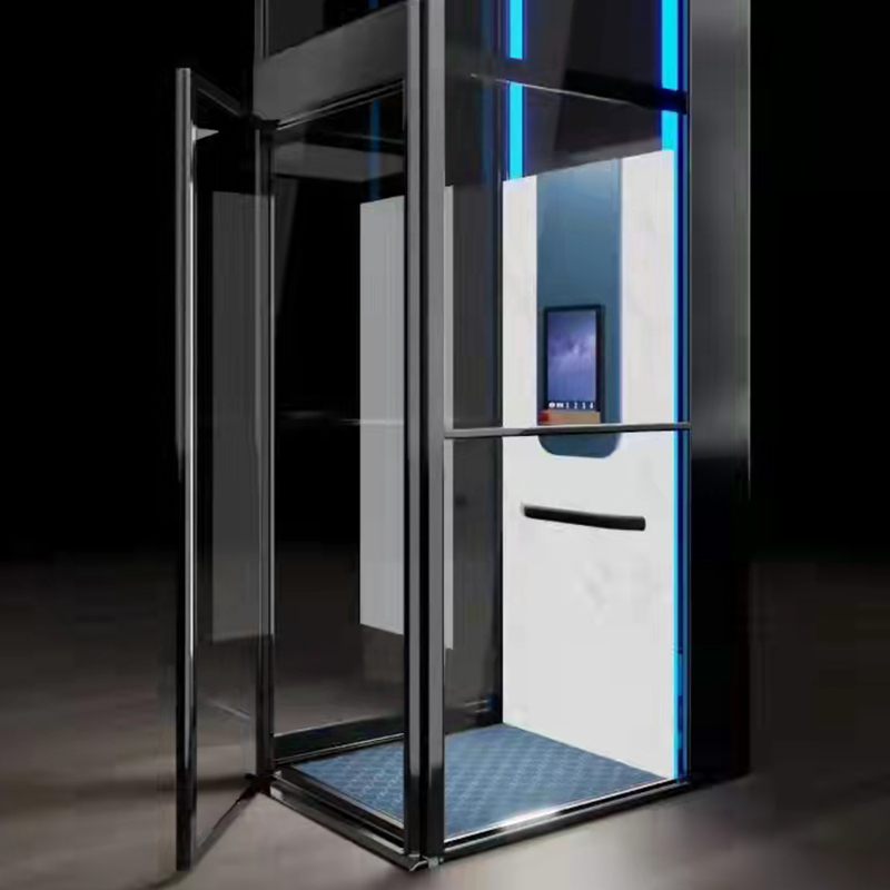 Custom Residential Traction Platform ElevatorA space-conscious traction home elevator with customizable dimensions, 250–1000 kg capacity and 2F–4F configurations for villas, duplexes and self-built houses.View Product →
Fitting MRL into Restricted Residential Spaces
MRL traction technology is most valuable when the building imposes limits. The answer is not to force one standard shaft into every home, but to match the elevator arrangement to the constraint.
- Limited overhead: verify top-of-shaft clearance, sheave position, and buffer space before assuming a standard MRL layout will fit.
- Shallow pit: a low-pit design may reduce excavation, but drainage, finishing, and safety clearances still need confirmation.
- Narrow shaft: gantry and platform layouts may use the plan more efficiently, yet door width and car size must remain practical.
- Existing house: retrofit work must consider how equipment reaches the site, how the shaft is supported, and where the controller can be serviced.
Service Access, Safety, and Code Checks
Controller placement is a safety and maintenance issue, not only a visual one. A cabinet that is hard to inspect may turn a minor adjustment into a major disruption. Before approving a layout, confirm the following points with the manufacturer and local code professional.
- The cabinet door opens fully without blocking stairs, doors, or emergency routes.
- Technicians have safe standing space and adequate lighting for inspection.
- Ventilation and heat dissipation match the controller specification.
- Cable entries are protected from water, dust, and damage during cleaning or renovation.
- Emergency operation and isolation points remain identifiable and reachable.
- Noise and vibration from the controller do not transfer into bedrooms or living areas.
- All clearances follow the approved elevator drawings and applicable local requirements.
Key planning rule: an MRL elevator saves space only when the hoistway, controller, and service zone are designed as one system. A compact shaft with an inaccessible controller is not a successful space plan.
What to Confirm Before You Choose an MRL Home Elevator
Use a short checklist to compare proposals on equal terms. The lowest shaft footprint is not always the best whole-home solution.
- Confirm shaft width, depth, overhead, and pit dimensions from a site survey.
- Ask for the exact controller location and cabinet dimensions.
- Review service clearance and the route technicians will use.
- Check heat, moisture, and dust conditions at the proposed controller position.
- Confirm car size, door width, and travel distance against daily household use.
- Review the maintenance plan, spare parts support, and emergency response procedure.
- Ensure the final layout is approved under the applicable local code and project requirements.
Frequently Asked Questions
Q1: Does an MRL elevator always place the controller inside the hoistway?
No. Machine roomless design removes the traditional machine room, but the controller may be shaft-mounted, placed in a landing cabinet, or located in an adjacent service space. The final position depends on the product, building layout, and maintenance access.
Q2: Can an MRL traction elevator fit a villa with no machine room?
Yes, that is the purpose of an MRL layout, but the villa still needs a suitable hoistway, overhead clearance, pit arrangement, and controller location. A site survey should confirm these conditions before the car size is fixed.
Q3: How much wall space does an MRL controller need?
Dimensions vary by model, so no single figure applies. Reserve space for the cabinet itself, a fully opening door, service standing room, ventilation, and cable entry. These items should appear on the approved layout drawing.
Q4: Is MRL the same as traction?
No. MRL describes the machine room arrangement. Traction describes the drive method. Many home MRL elevators use traction drive, but the two terms answer different questions and should not be used interchangeably.
For a private home, the strongest MRL design is the one that removes unnecessary building volume while keeping the controller reachable, the car practical, and the shaft buildable. Spatial savings should be measured across the whole project, including the landing wall and service zone.
Dong'ao Home Elevator approaches MRL planning around the actual villa or retrofit condition, so the hoistway, controller position, and maintenance route are considered together rather than added after the car has been chosen.
-
 Founding Road, Qidu Linhu Economic Zone, Wujiang City, Jiangsu Province, China
-
 [email protected]
-
 +86 15301576876/+86 0512-63818375
QR CODE

